introduction to 3d drawing in core animation
In this tutorial I'thou going to introduce you to the techniques used to draw 3D stuff with Core Animation.
The good news are Core Animation tin can aid us achieve some 3D goodness without using OpenGL directly. In that location are bad news though: creating a circuitous 3D video game with Cadre Blitheness is non a good idea.
In the beginning part of this tutorial we'll discuss some 3D theory and we'll create some simple 3D scenes using the concepts described.
In the second part we'll apply Core Animation to create a 3D scene that should remind you the interface used in a carousel image gallery.
Here'southward a preview of the final app in action.
Set up? Allow's become the coding started!
First, download the code at the finish of the article. If you want to create your ain project remember to add together the QuartzCore framework to information technology.
3D and Matrices (a scrap of math… but just a scrap!)
Drawing into a 3D infinite means adding depth to the standard X and Y second infinite we are used to in iOS. This results in a tertiary axis called Z.
In that infinite nosotros can motility an object vertically, horizontally and by depth simply by irresolute its 10,Y,Z coordinates.
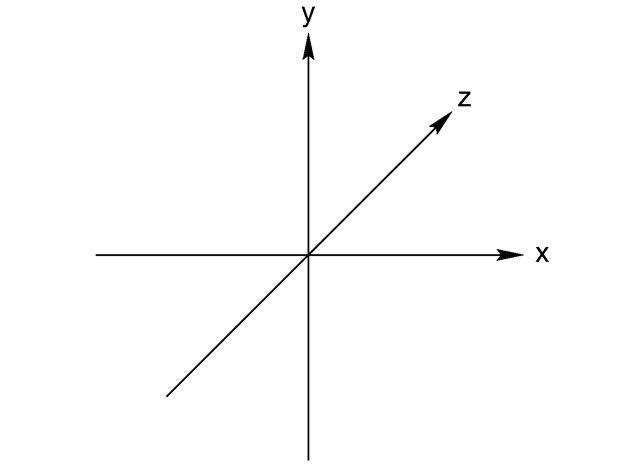
Performing transformations similar translation, calibration and rotation to an object in a second or 3D space needs some math calculations.
Using matrices is the right way to implement these operations.
You can think of a matrix as a grid of values in some ways similar to a multi dimensional assortment.
For example, in 3D spaces we apply a 4X4 Matrix like this:
            [X][0][0][0]
            [0][Y][0][0]
            [0][0][Z][0]
            [0][0][0][1]
Multiplying this matrix by the coordinate of each indicate of an object (in 3D they are also chosen vertices), we obtain a transformation of the original object.
To be precise the previous matrix is used to perform the calibration operation, where X, Y and Z represent the scale values that y'all want to apply for each axis.
If you need to perform other transformations, like rotation or translation, you lot'll take to ready the matrix with a unlike scheme.

Fear not, you don't need to know more than that and yous are not supposed to do this operation direct. Core Animation does it for yous in a totally opaque way.
Personally, I feel more confident with my code if I know how it works in the background (the basics of it, at least). Then if you want to know more than most matrices I propose you to take a look at this article.
3D Transformations
At present that you lot have a bones idea of what a matrix does and how a 3D space is organised let'southward do some 3D stuff using Core Animation.
Open the file TB_3DIntro->viewController.m.
I have listed six functions prefixed with A,B,C,D,East, or F. Each part creates a unlike 3D scene.
Let'due south see the scene created by the function A_singlePlan.
With this function nosotros are going to describe a plan rotated past 45 degrees on the Y axis.
Beginning, nosotros create a CALayer that nosotros apply as container (it is not required, but I prefer not to piece of work directly with the first view'due south layer).
- (void)A_singlePlane{ //Create the container CALayer *container = [CALayer layer]; container.frame = CGRectMake(0, 0, 640, 300); [self.view.layer addSublayer:container]; So nosotros create another CALayer to represent a airplane.
//Create a Airplane CALayer *purplePlane = [cocky addPlaneToLayer:container size:CGSizeMake(100, 100) position:CGPointMake(100, 100) colour:[UIColor purpleColor]]; I've built a simple helper function which adds the aeroplane to the container layer directly so returns the new plane layer. Its code is extremely simple:
-(CALayer*)addPlaneToLayer:(CALayer*)container size:(CGSize)size position:(CGPoint)indicate color:(UIColor*)color{ //Initialize the layer CALayer *aeroplane = [CALayer layer]; //Define position,size and colors plane.backgroundColor = [colour CGColor]; plane.opacity = 0.vi; airplane.frame = CGRectMake(signal.x, point.y, size.width, size.summit); plane.borderColor = [[UIColor colorWithWhite:i.0 alpha:0.5]CGColor]; plane.borderWidth = 3; plane.cornerRadius = 10; //Add together the layer to the container layer [container addSublayer:plane]; return plane; } And finally we add together the transformation using a CATransform3D.
What'south a CATransform3D??? Cmd+click on the data type name and yous become that it's a structure which correspond a matrix using an "exotic" syntax 😛
struct CATransform3D { CGFloat m11, m12, m13, m14; CGFloat m21, m22, m23, m24; CGFloat m31, m32, m33, m34; CGFloat m41, m42, m43, m44; }; typedef struct CATransform3D CATransform3D; The lawmaking of the transformation function is extremely elementary:
//Apply the transform to the Aeroplane CATransform3D t = CATransform3DIdentity; t = CATransform3DRotate(t, 45.0f * M_PI / 180.0f, 0, 1, 0); purplePlane.transform = t; } The first step is to initialize the transformation using the identityMatrix (CATransform3DIdentity), that is nothing more than than a neutral value (like 0 for the sum) and we multiply that by a rotation matrix using the function CATransform3DRotate.
This function takes a starting matrix, the bending of the rotation (in radians) and the influence over the 3 axis. In the instance 10 and Z are non influenced by the rotation while the Y is totally influenced… that only ways that the object rotates by 45° around the Y centrality.
This is the scene produced by this first example.
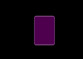
Uhm… every bit you lot can see it doesn't look 3D at all! We accept just a square squeezed on the Ten axis.
The problem is that we haven't specified a perspective value. Ordinarily a 3D scene is drawn using a Orthographic projection that creates a flattened representation of the scene. In other words in an orthographic projection you lot tin can't notice the depth produced by the Z axis.
To add depth to our scene we have to alter the param m34 of the transform matrix. This parameter defines the perspective value.
Let'south move to the function B_singlePlanePerspective to see how it works.
The code of this function is identical to the previous part except for the transformation part:
//Employ transformation to the Aeroplane CATransform3D t = CATransform3DIdentity; //Add the perspective!!! t.m34 = i.0/ -500; t = CATransform3DRotate(t, 45.0f * M_PI / 180.0f, 0, 1, 0); purplePlane.transform = t; As you tin can see we can directly admission the m34 property and assign it an capricious value.
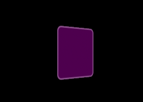
I won't go deeper in math explanation about how this value is going to alter the scene, simply let'southward say that the closer it is to 0 the deepest is the perspective.
Here the upshot of this code with 2 unlike perspective values:

3D Transformations chain
To perform more than than 1 transformation on an object we can perform multiplication of matrices.
For example if we desire to translate and rotate an object we can obtain a transformation matrix just multiplying two matrices:
TransformMatrix = TranslateMtx * RotateMtx In arithmetic we are used to apply the commutative property:
TranslateMtx * RotateMxt = RotateMtx * TranslateMtx
But Matrix multiplication is non commutative! And so AxB could be different from BxA. This is a actually of import point to keep in mind!
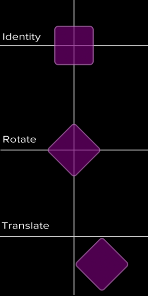
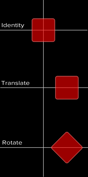
In the next example (part C_transformationsChain) nosotros are going to perform the same transformations on 2 objects just changing the order with which those transformations are practical. Here'due south the primary lawmaking:
//Utilise transformation to the PLANES CATransform3D t = CATransform3DIdentity; //Purple plane: Perform a rotation and and so a translation t = CATransform3DRotate(t, 45.0f * M_PI / 180.0f, 0, 0, one); t = CATransform3DTranslate(t, 100, 0, 0); purplePlane.transform = t; //reset the transform matrix t = CATransform3DIdentity; //Cerise plane: Perform translation showtime and then the rotation t = CATransform3DTranslate(t, 100, 0, 0); t = CATransform3DRotate(t, 45.0f * M_PI / 180.0f, 0, 0, 1); redPlane.transform = t; And now accept a await at the consequence
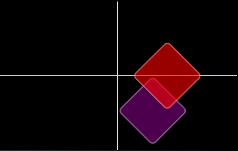
Every bit y'all tin run across the gild of the transformation radically changes the way the 2 objects are placed in space.
Let's focus on the PurplePlane: In this instance the rotation changes its axis orientations.
Side by side nosotros translate the PurplePlane on a X axis that is oriented in a dissimilar style respect to the RedPlane axis.
Check these images to better sympathize how the transformations have place.
Work with layer hierarchies
Take you noticed that until at present nosotros have applied transformations directly to the planes? In a 3D scene information technology is often useful to create hierarchies of objects and applying transformations to the root of the bureaucracy, transforming and so the whole structure.
Let'due south take the case produced past the function D_multiplePlanes.
We add together 4 planes to the container.
Without any transformations the scene would wait like this:

Adding a rotation to the Y axis to each plane we obtain 4 distinct rotations:
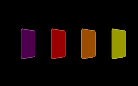
Simply performing the rotation on the container nosotros get a totally unlike scene:

Nosotros can think of this terminal scene equally the result of a camera position change. So we are non moving each plane but we are changing our indicate of view.
I write here the part of the function that applies the transformations to the planes or to the container:
//Transformation CATransform3D t = CATransform3DIdentity; BOOL applyToContainer = NO; //Apply the transformation to each Plane if(!applyToContainer){ t.m34 = 1.0 / -500.0; t = CATransform3DRotate(t, degToRad(60.0), 0, 1, 0); purplePlane.transform = t; t = CATransform3DIdentity; t.m34 = one.0 / -500.0; t = CATransform3DRotate(t, degToRad(60.0), 0, 1, 0); redPlane.transform = t; t = CATransform3DIdentity; t.m34 = 1.0 / -500.0; t = CATransform3DRotate(t, degToRad(60.0), 0, 1, 0); orangePlane.transform = t; t = CATransform3DIdentity; t.m34 = 1.0 / -500.0; t = CATransform3DRotate(t, degToRad(lx.0), 0, 1, 0); yellowPlane.transform = t; } //Apply the transformation to the CONTAINER else{ CATransform3D t = CATransform3DIdentity; t.m34 = 1.0/-500; t = CATransform3DRotate(t, degToRad(threescore.0), 0, i, 0); container.transform = t; } Work with CATransformLayer
What nosotros take seen and so far works correctly, but to be honest the CALayer is not the right choice equally the root of a 3D hierarchy.
The function E_multiplePlanesZAxis is going to show us why.
In this scene we create four planes at the same X, Y coordinates but with different Z.
The purplePlane turns out to exist the closest to your indicate of view and the YellowPlane the uttermost.
//Use transforms to the PLANES t = CATransform3DIdentity; t = CATransform3DTranslate(t, 0, 0, -ten); purplePlane.transform = t; t = CATransform3DIdentity; t = CATransform3DTranslate(t, 0, 0, -50); redPlane.transform = t; t = CATransform3DIdentity; t = CATransform3DTranslate(t, 0, 0, -90); orangePlane.transform = t; t = CATransform3DIdentity; t = CATransform3DTranslate(t, 0, 0, -130); yellowPlane.transform = t; Before creating these planes, we apply a rotation to the container every bit we did in the previous example.
//Apply transform to the CONTAINER CATransform3D t = CATransform3DIdentity; t.m34 = one.0/-500; t = CATransform3DRotate(t, fourscore.0f * M_PI / 180.0f, 0, i, 0); container.transform = t; You'd probably expect to run into something like this:

We obtain this instead 🙁

This is due to the fact that a CALayer is incapable of managing the depth of a 3D hierarchy and information technology just flattens the scene to a single Z level.
To correct this problem and obtain the right result, we take to choose a CATransformLayers as root object.
Check the function F_multiplePlanesZAxis which fixes the trouble:
//Create the container equally a CATransformLayer CATransformLayer *container = [CATransformLayer layer]; container.frame = CGRectMake(0, 0, 640, 300); [cocky.view.layer addSublayer:container]; Think that the CATransformLayer is a special layer. Unlike CAlayers only its sublayers are rendered and properties like backgroundColor, contents, border etc are totally ignored.
The first part of this tutorial is finished. I advise you to play with these functions and, why not, try to use the scale transformation using CATransform3DScale that I haven't shown you in this tutorial.
If you have whatever questions you can discover me on twitter @bitwaker.
Source: https://www.thinkandbuild.it/introduction-to-3d-drawing-in-core-animation-part-1/
0 Response to "introduction to 3d drawing in core animation"
Post a Comment